ThreePhase Brushless DC Motor Control System Download Scientific Diagram
Introduction. MPS recently released an integrated, compact gate driver circuit with six power MOSFETs. This article discusses the MP6540 series, including the MP6540A, MP6540H, and the MP6540HA.The MP6540 is a 3-phase, brushless DC (BLDC) motor driver that integrates three half-bridges consisting of six N-channel power MOSFETs.. Conventional motor driver architecture combines a motor driver.
Sensored brushless DC motor control with Arduino Simple Circuit
A brushless DC electric motor (BLDC motor or BL motor) are synchronous motors powered by direct current (DC) electricity via an inverter or switching power supply which produces electricity in the form of alternating current (AC) to drive each phase of the motor via a closed-loop controller.
Brushless Dc Motor Schematic My XXX Hot Girl
ST's STSPIN drivers for 3-phase brushless DC (BLDC) motors includes power drivers in a 3-phase bridge configuration and integrated solutions with built-in decoding logic for Hall-effect sensors. Our BLDC motor controllers also feature a PWM current controller to autonomously drive a BLDC motor through motion commands coming from the motor or.

“3 phase brushless dc motor” “3 phase brushless dc motor controller
Competitive Pricing on Millions of Electronic Components. Request a Quote Today. Find Pricing and Specs for Driver Solutions at Digikey!

Brushless DC Motor Construction, Working Principle and Advantages
1. High Voltage DC Motor Speed Regulator Circuit 2. Solid State Contactor Circuit for Motor Pumps 3. Constant Torque Motor Speed Controller Circuit 4. How to Interface Servo motors with Arduino 5. How to Control Motor with a Cell Phone 6.
Brushless motor drive circuit Toshiba Electronic Devices & Storage
4.4 V to 30 V, 15 A, High Performance Brushless DC Drone Propeller Controller Reference Design Overview A fully assembled board has been developed for testing and performance validation only, and is not available for sale. Design files & products Design files Download ready-to-use system files to speed your design process. TIDUAK1.PDF (14975 K)
15V to 60V ThreePhase Brushless DC Motor PreDriver Electronics
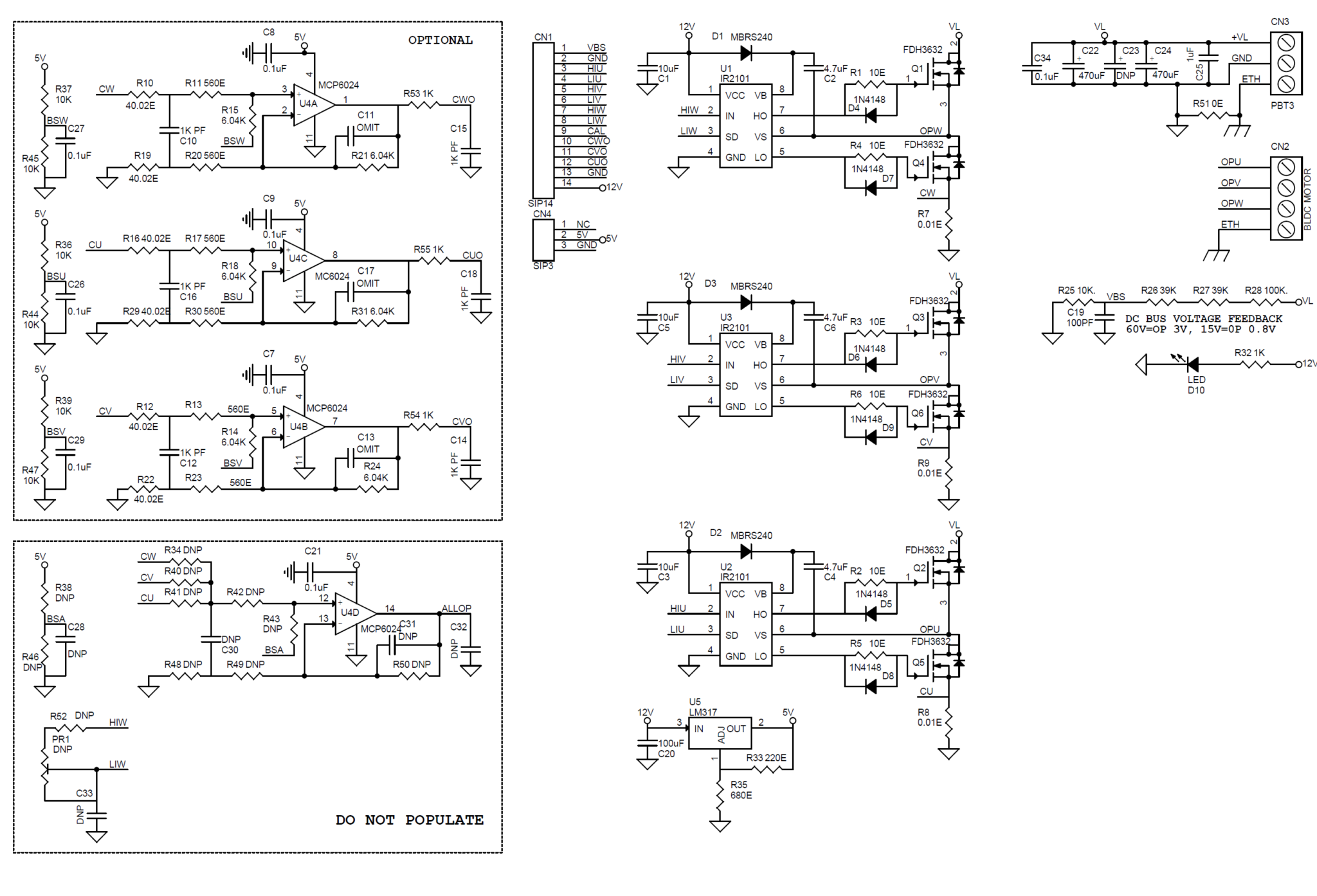
The L6235 is a fully integrated motor driver IC specifically developed to drive a wide range of BLDC motors with Hall effect sensors. This IC is a one-chip cost effective solution that includes several unique circuit design features.
What is a Brushless DC Motor Overview and Advantage Saw Features
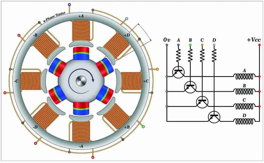
Trapezoidal commutation is the most basic method of spinning a 3-phase Brushless-DC motor. This is accomplished by energizing the windings in a 6-step pattern every 60 electrical degrees so that one phase souring motor current, another phase is sinking motor current, and the last phase remains unconnected (Hi-Z).
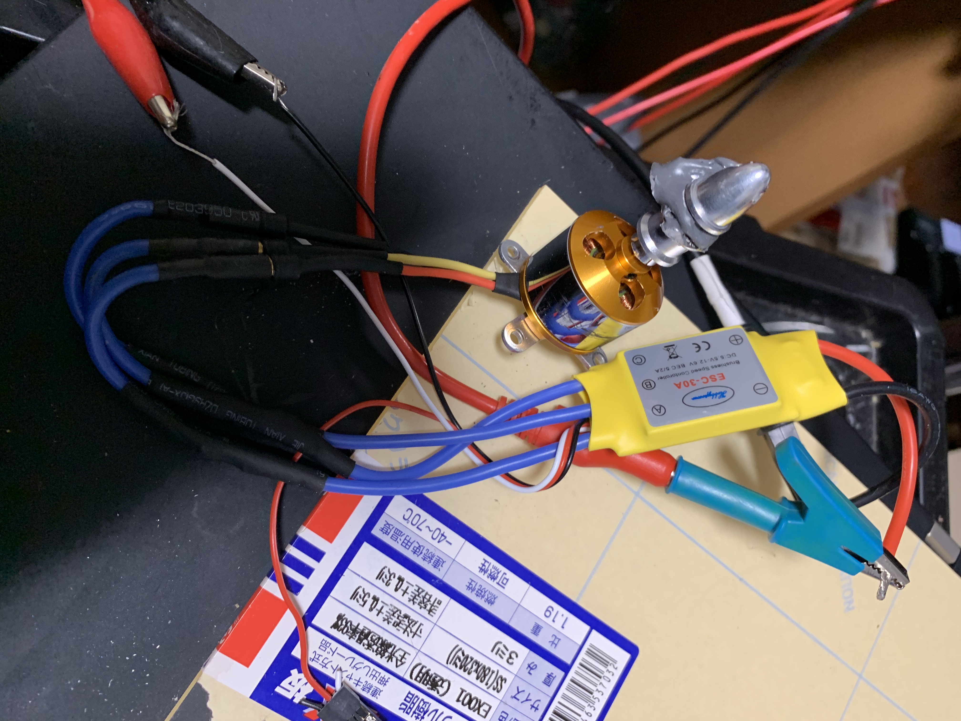
41J Blog » Blog Archive » ESC30A Brushless DC motor driver Notes
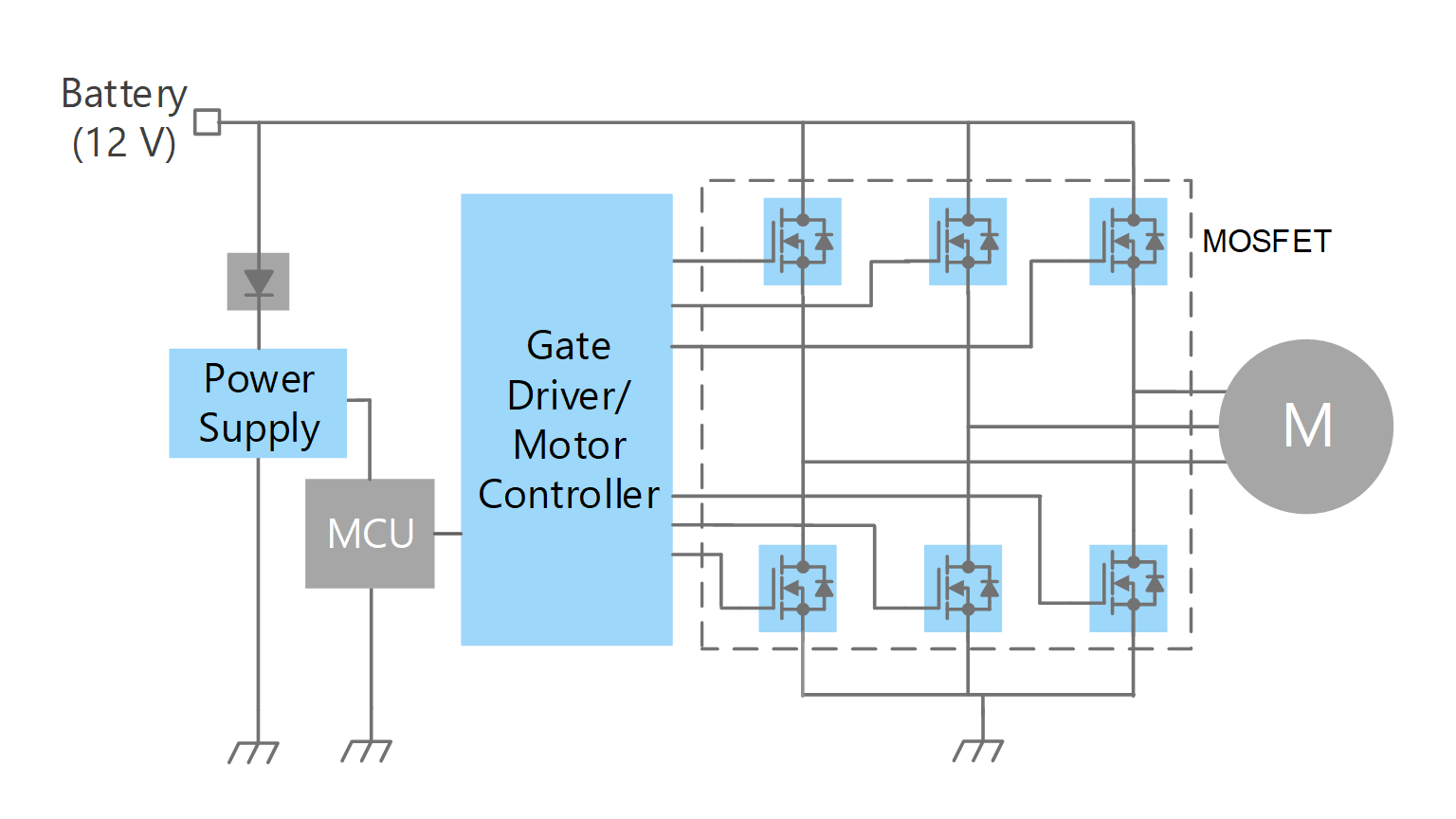
high, one motor terminal driven low, and one motor ter-minal left floating. A simplified drive circuit is shown in Figure 3. Individual drive controls for the high and low drivers permit high drive, lo w drive, and floating drive at each motor terminal. One precaution that must be taken with this type of driver circuit is that both high side

What is Brushless DC Motor (BLDC) and How to Control it with Arduino
1. Simple Drill Speed Controller Circuit - 220V, 120V AC Back EMF Dependent 2. How To Make a Fan Speed Controller for Heatsink 3. Automatic Sliding Door Circuit 4. Simple DC Motor Speed Controller Circuit 5. Simple 12V DC Fan Speed Controller Using IC 555 6. Model Train Controller Circuit
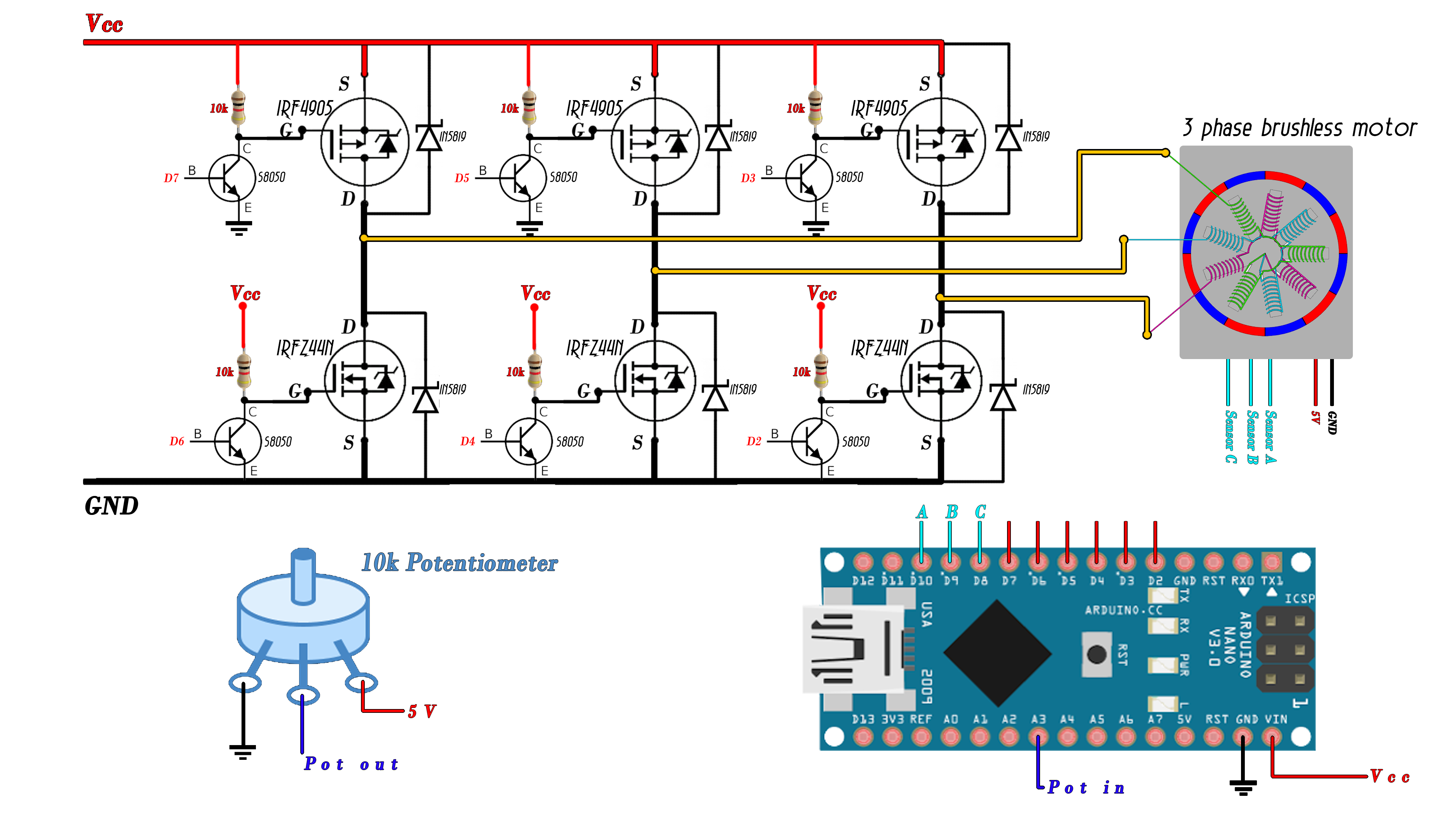
Brushless sensored schematic
BLDC motors are a type of synchronous motor. This means the magnetic field generated by the stator and the magnetic field generated by the rotor rotate at the same frequency. BLDC motors do not experience the "slip" that is normally seen in induction motors. BLDC motors come in single-phase, 2-phase and. 3-phase configurations.

Brushless Dc Motor Controller Wiring Diagram Chicic
The brushless DC (BLDC) motor's increasing popularity is due to the use of electronic commutation. This replaces the conventional mechanics comprised of brushes rubbing on the commutator to energize the windings in the armature of a DC motor.

Brushless Dc Motor Driver Circuit Diagram
In a BDC motor, this is a mechanical process triggered by a commutator with brushes. In a BLDC motor, it happens electronically with the help of transistor switches. BLDC motor working principle

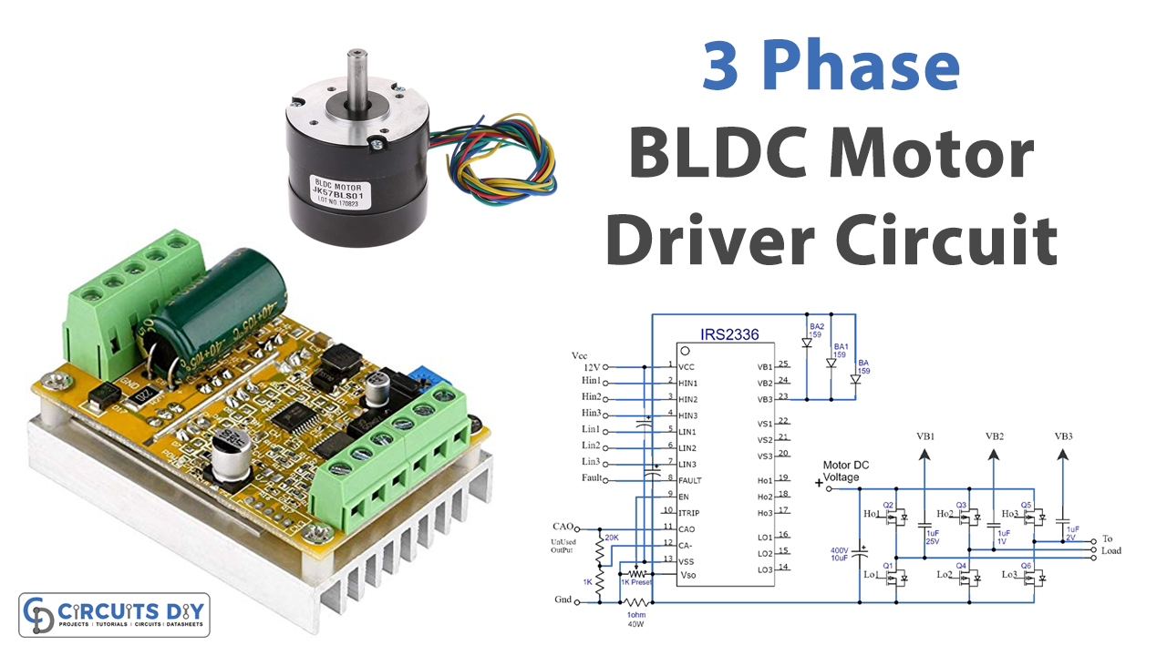
(BLDC) Brushless DC Motor Driver Circuit using 555 IC
5A. It can be used in a very wide range of applications. It has been realized in Multipower BCD60II technology which allows the combination of isolated DMOS transistors with CMOS and Bipolar circuits on the same chip. It is available in Power DIP 20 (16+2+2) and in Power SO 20 packages.
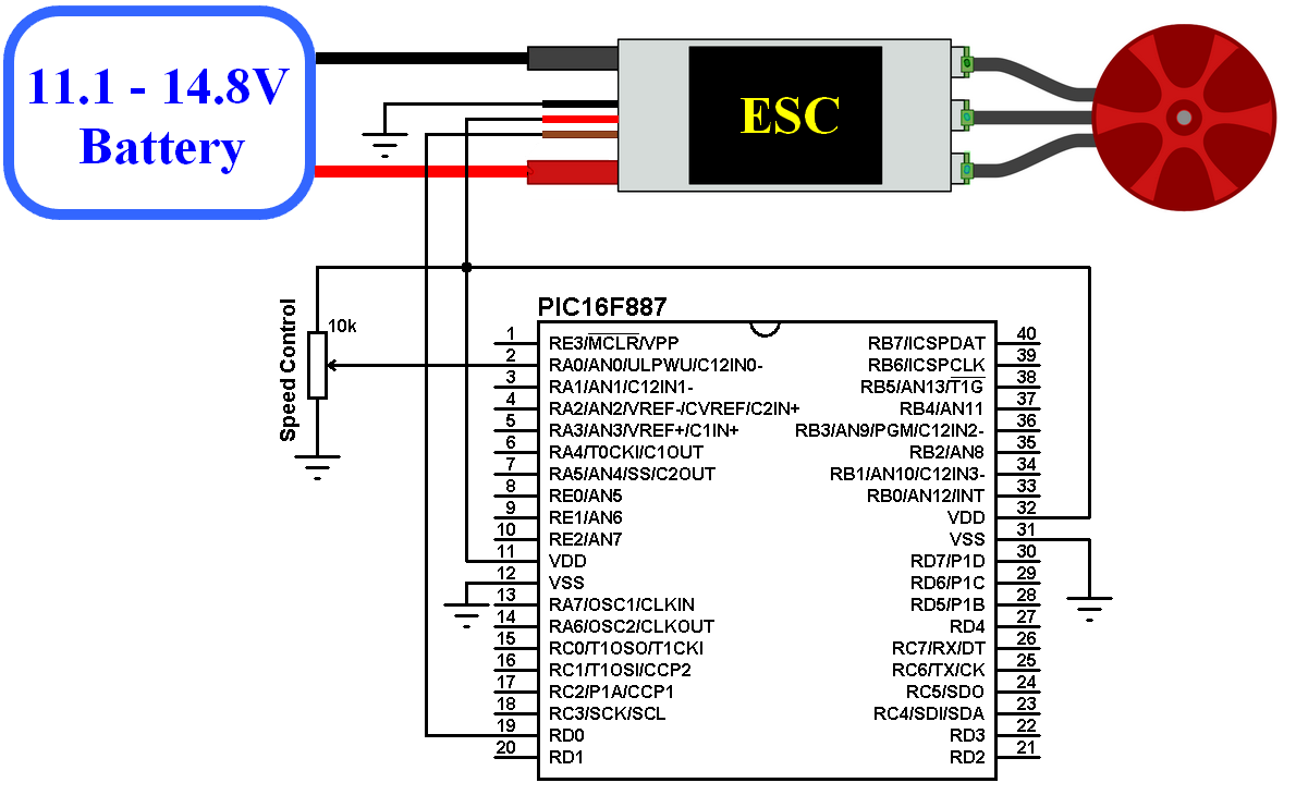
Sensorless brushless DC motor drive with an ESC and PIC16F887
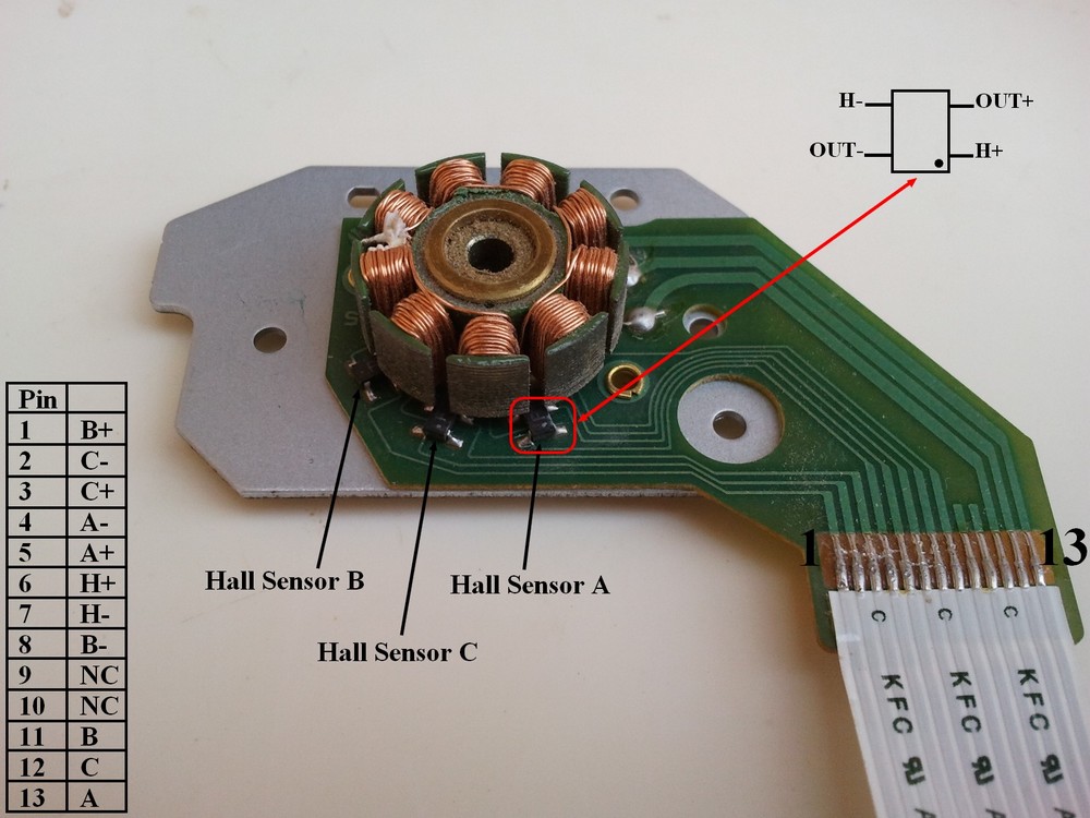
December 15, 2020 119085 - Advertisement - Use of brushless DC motors ( BLDCs) is on the rise. But their control usually requires rotor position information for selecting the appropriate commutation angle. Normally, a Hall Effect sensor is used to sense rotor position.

Brushless Dc Motor Controller Circuit Diagram
Then using the write () function we send the signal to the ESC, or generate the 50Hz PWM signal. The values from 0 to 180 correspond to the values from 1000 to 2000 microseconds defined in the setup section. So, if we upload this code to our Arduino, and then power up everything using the battery, then we can control the speed of the brushless.